Reshape/Replace Component Geometry
This section provides an overview on how to manage your spatial features within the Metrix Asset Management system. The context covered includes:
Spatial features can be shared by more than one component. Remember to check if the feature you are modifying is shared and if this has any effect on you doing so.
Reshaping an existing Component Spatial Feature
-
To alter the spatial feature of a component, select the asset and navigate to the appropriate component info panel.
-
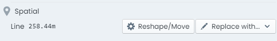
Within the component info panel, is a section titled ‘Spatial’. To modify the current geometry without changing the geometry type (point, line, polygon), click ‘Reshape/Move’.
-
The info panel will hide itself and you will be immersed into the geometry editing view.
-
Make the desired edits to your geometry, according to its type of point or line/polygon.
-
When finished, click ‘End Editing’ on the panel at the top of the map window.
-
The updated geometry is now STAGED and ready to save.
Replacing an existing Component Spatial Feature
-
To replace the spatial feature of a component, select the asset and navigate to the appropriate component info panel.
-
Within the component info panel, is a section titled ‘Spatial’. To replace the current geometry by changing the geometry type (point, line, polygon), click the ‘Replace With’ menu.
-
From the menu list, choose the desired geometry type for the new spatial feature - point, line, or polygon.
-
The info panel will hide itself and you will be immersed into the geometry editing view.
-
Create the desired geometry type as either a point or line/polygon.
-
When finished, click ‘End Editing’ on the panel at the top of the map window.
-
The replaced geometry is now STAGED and ready to save.
For more information, see the helpful tutorial video below.
Confirming Shared Spatial Features
-
To confirm whether or not an active component spatial feature is shared with other components on the asset record, navigate to the parent asset info panel.
-
Within the parent asset info panel is a section titled ‘Component Spatial Breakdown’. This displays a table view specifying each asset component alongside the geometry number* that the component is using.
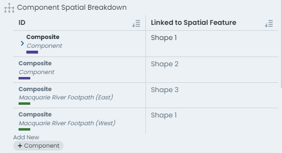
In the above screenshot, the asset has four (4) components, and three (3) unique spatial features. The first and last component (in the table view) are using ‘Shape 1’* and the middle two components reference their own shape. We therefore know that ‘Shape 1’ is shared across those two components.
* this number is dynamically generated and simply serves to inform whether a shape feature is used on more than one component.
Modifying Point Features
Point features support relocation.
Moving Points To move a point, simply:
- Click once on its current location (it will change color to bright green).
- Click-and-drag the feature from where it currently is, to where you wish it to be located.
- Release to finish relocating.
When finished, click ‘End Editing’.
Modifying Lines & Polygons
Line/Polygon features support both relocation and reshaping.
Moving Lines/Polygons To move a line or polygon, simply:
- Click once on any of the line/perimeter segments.
- Click-and-drag (from that segment). The entire shape will begin to follow your cursor across the map.
- Release to finish relocating.
Reshaping Lines/Polygons
To reshape a line or polygon, simply:
- Click once on any of the line/perimeter vertex nodes (it will change color to bright green).
- Click-and-drag (from that vertex node) from where it currently is, to where you wish it to be located.
- Release to finish relocating the node.
- Repeat the above for other vertex nodes that need moving.
- To ADD a new vertex node, click once on one of the segment center marker (white dot).
- A new vertex node will be created, click-and-drag it to the desired location.
- Release to finish relocating.
Creating Point Features
To create a new point feature:
- Simply click on the map window where you want the point to be located.
- To alter this location after initial placement, follow the instructions to relocate a point
Creating Line & Polygons
To create a new line or polygon feature:
- Click on the map window where you want the first vertex node to be located.
- Then, continue to click map locations for each subsequent vertex node location.
- Double-click to finish drawing new vertex nodes.
- To alter the location of a vertex node after initial placement, follow the instructions to relocate a line/polygon