The ability to split an Asset is vitally important in keeping the Organisation’s financial reporting,
engineering concepts, and asset management data policies in sync. This section provides an overview
on two different methods supported by the Metrix Asset Management system to perform spatial,
linear bisections of your assets or asset components.
For a basic overview of how splitting works, please see the video below:
Subsections of Splitting Assets or Components
Split Assets
To perform a spatial split of an asset and its components, follow these steps:
Navigate to the main ‘Assets’ page and make a
selection
from the map screen.
Info
For splitting assets, a particular component selection within the asset is not relevant.
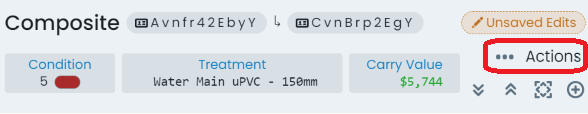
At the top of the info panel, click the ‘Actions’ menu.
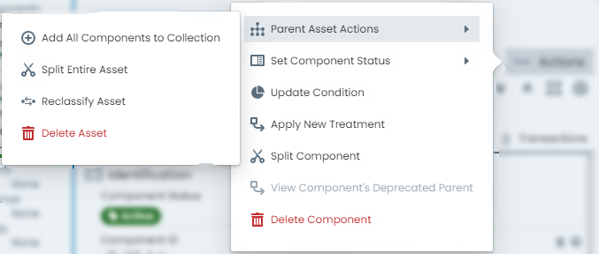
From the ‘Actions’ menu options, hover or select ‘Parent Asset Actions’ and then choose
‘Split Entire Asset’.
A fly-out panel wil appear with tools ready for you to perform the split operation. Refer to
the section on
Splitting Tools
for an overview of this panel.
Draw a split line across your asset in the panel’s map window. Double-click to finish drawing.
Info
Make sure the splitting plane you digitise, crosses the original asset at least once.
Note also, you can split a single feature MULTIPLE times by drawing in a ‘zig-zag’ fashion.
This is a great way to create more than two (2) sub-features.
Below the map window, use the calendar control to enter the desired posting date which will
be used when apportioning any capital value across the split results.
Once the posting date is selected, the system will prepare a preview of the split that would
be required to suit.
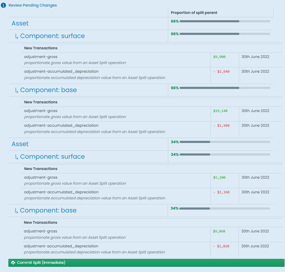
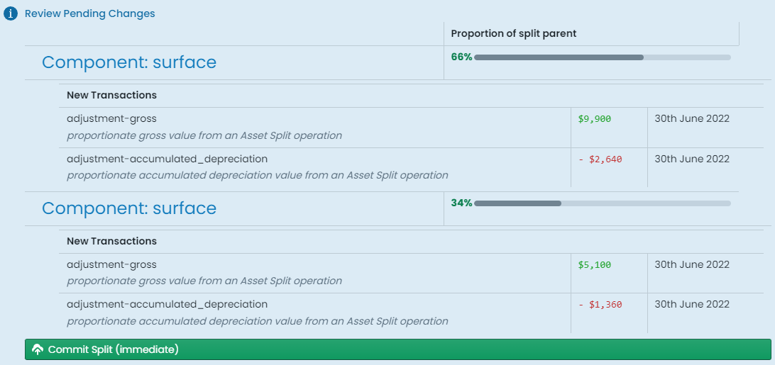
Two or more - depending on the pattern of your digitised split line - asset records, with
relevant child components, will be rendered for your review. Each asset and component displays
the percentage share that they will demand from the original asset. Further to this, this share
is used to calculate the proportion of capital value that each asset component will receive.
When you are happy with the previewed results, click ‘Commit Split (immediate)’
This operation does NOT proceed via staged changes, and occurs immediately. You have successfully
split your asset and its sub-components.
Split Components
To perform a spatial split of a single asset component, follow these steps:
Navigate to the main ‘Assets’ page and make a
selection
from the map screen.
Info
Make sure you have the correct component selected - the one you wish to split
At the top of the info panel, click the ‘Actions’ menu.
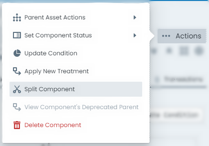
From the ‘Actions’ menu options, choose ‘Split Component’.
A fly-out panel wil appear with tools ready for you to perform the split operation. Refer to
the section on
Splitting Tools
for an overview of this panel.
Draw a split line across your component in the panel’s map window. Double-click to finish drawing.
Info
Make sure the splitting plane you digitise, crosses the original component at least once.
Note also, you can split a single feature MULTIPLE times by drawing in a ‘zig-zag’ fashion. This is
a great way to create more than two (2) sub-features.
Below the map window, use the calendar control to enter the desired posting date which will
be used when apportioning any capital value across the split results.
Once the posting date is selected, the system will prepare a preview of the split that would
be required to suit.
Two or more - depending on the pattern of your digitised split line - component records will be
rendered for your review. Each component displays the percentage share that they will demand from
the original component. Further to this, this share is used to calculate the proportion of capital
value that each component will receive.
When you are happy with the previewed results, click ‘Commit Split (immediate)’
This operation does NOT proceed via staged changes, and occurs immediately. You have successfully
split your component.
Explode Multi-Part Features
Multi-geometry spatial features are supported within the Metrix Asset Management system. Sometimes
however, it can become necessary to de-aggregate such features into their constituent building blocks.
This document provides an overview on how to perform such de-aggregation (explode) of geometries
in the system.
Info
Geometry explosion is a COMPONENT level tool. Even if the spatial feature is shared across many
asset components, this operation will only create single-part geometry features for your active
component.
Any components also sharing the multi-geometry will continue to reference the multi-geometry.
Navigate to the main ‘Assets’ page and make a
selection
from the map screen.
Info
Make sure you have the correct component selected - the one you wish to explode
At the top of the info panel, click the ‘Actions’ menu.
From the ‘Actions’ menu options, choose ‘Split Component’.
A fly-out panel wil appear with tools ready for you to perform the operation. At the top
of the panel, choose ‘Explode’.
Use the calendar control to enter the desired posting date which will be used when
apportioning any capital value across the exploded results.
Once the posting date is selected, the system will prepare a preview of the explosion that would
be required to suit.
Two or more - depending on the original multi-geometry - component records will be
rendered for your review. Each component displays the percentage share that they will demand from
the original feature. Further to this, this share is used to calculate the proportion of capital
value that each component will receive.
When you are happy with the previewed results, click ‘Commit Split (immediate)’
This operation does NOT proceed via staged changes, and occurs immediately. You have successfully
exploded your component.
Split Tools
This document provides a brief overview of the splitting
asset and/or
components tools,
and how to use them to generate a valid splitting plane.
The following tools are discussed:
Drawing your Splitting Plane
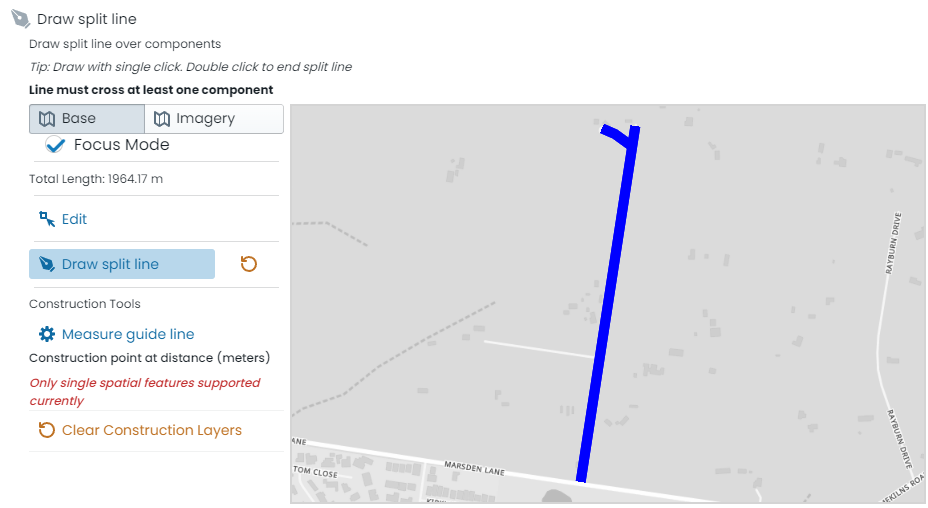
To draw the splitting plane:
Click on ‘Draw split line’.
In the map window, click to start the splitting plane.
Move the cursor and click again to add vertex nodes to your splitting plane.
To finish, double-click.
To clear the splitting plane and redraw, simply click the redo button next to the ‘Draw split line’ button.
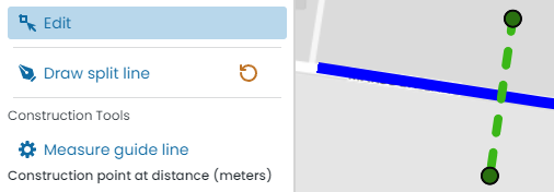
Info
Once drawn, the splitting plane can be edited. Simply click ‘Edit’ and then manage the splitting plane
following these directions.
Measure Guide Line
The splitting panel provides users with the option to generate ‘construction lines’ before committing their split
plan. These ‘construction lines’ will reveal their length for added context for the user. To use the measure tool:
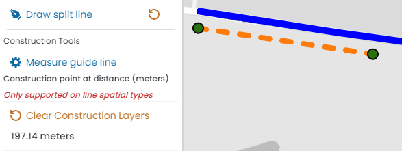
Click on ‘Measure guide line’.
In the map window, click to start the construction line.
Move the cursor and click again to add vertex nodes to your construction line.
To finish, double-click.
The length of your construction line will be calculated and displayed below.
The construction line(s) can be cleared by clicking ‘Clear Construction Layers’.
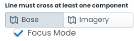
Map Context
The built-in map window in the split panel contains controls to toggle aerial imagery, basemaps, as well as the
Metrix mapping focus mode. Set these views accordingly to provide yourself with the required context to draw
the split plane.
For information about each setting, read below.
Focus Mode
For nearly all users, there exists a colour combination that is hard to decipher between and thus
difficult to read when displayed in a map window. To cater for this, the Metrix Asset Management
map tools provide users with the ability to put the map backdrop into ‘Focus Mode’. This will
binarise (to make black-and-white) the backdrop so that the colours of your asset portfolio are
easier to distinguish.
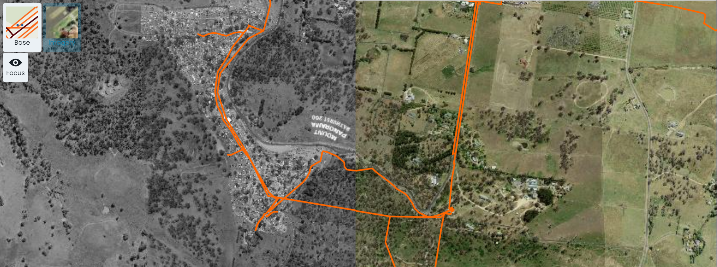
View Aerial Imagery as Backdrop
To view the aerial imagery as a backdrop to your asset portfolio, simply click on the ‘Imagery’
button in the top-left hand corner of the map window. This will swap out the underlying view to
the aerial photograph imagery configured for your environment. The screenshot below shows a map window
with aerial imagery as the backdrop, split between focus mode and standard.
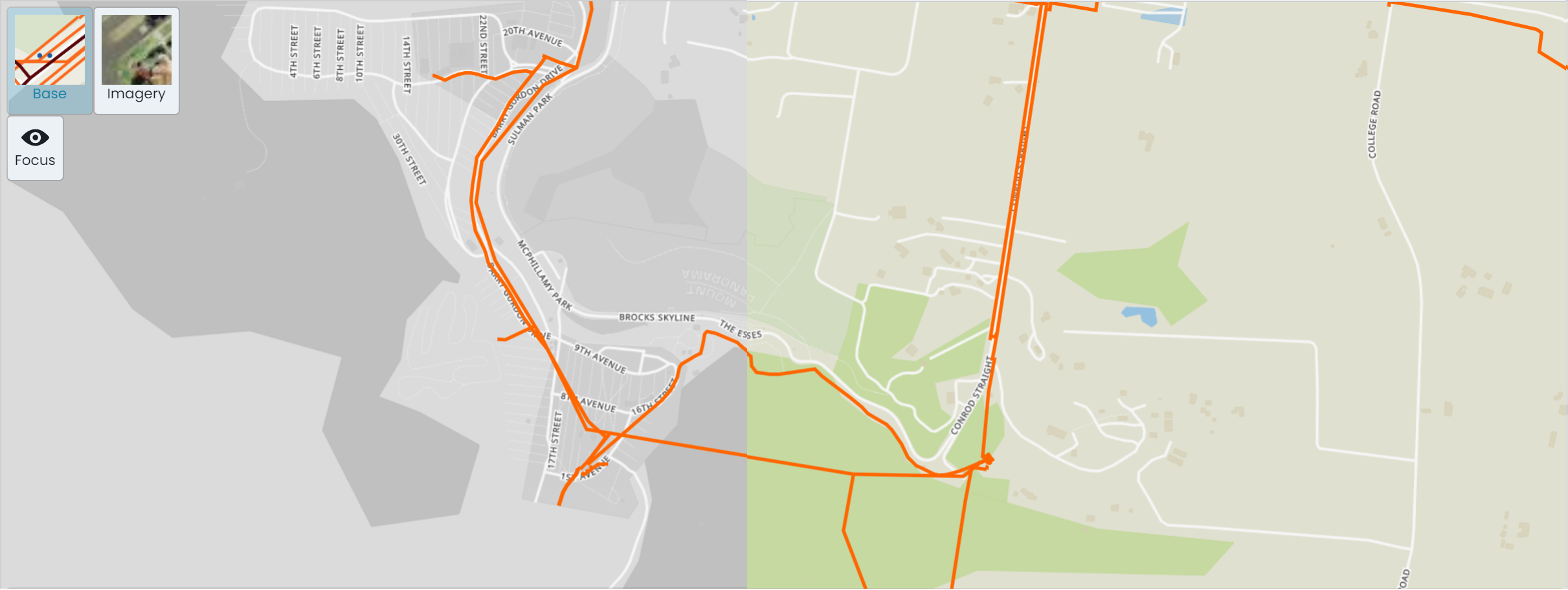
View Basemap as Backdrop
To view the basemap as a backdrop to your asset portfolio, simply click on the ‘Base’
button in the top-left hand corner of the map window. This will swap out the underlying view to
the basemap configured for your environment. The screenshot below shows a map window
with basemap as the backdrop, split between focus mode and standard.